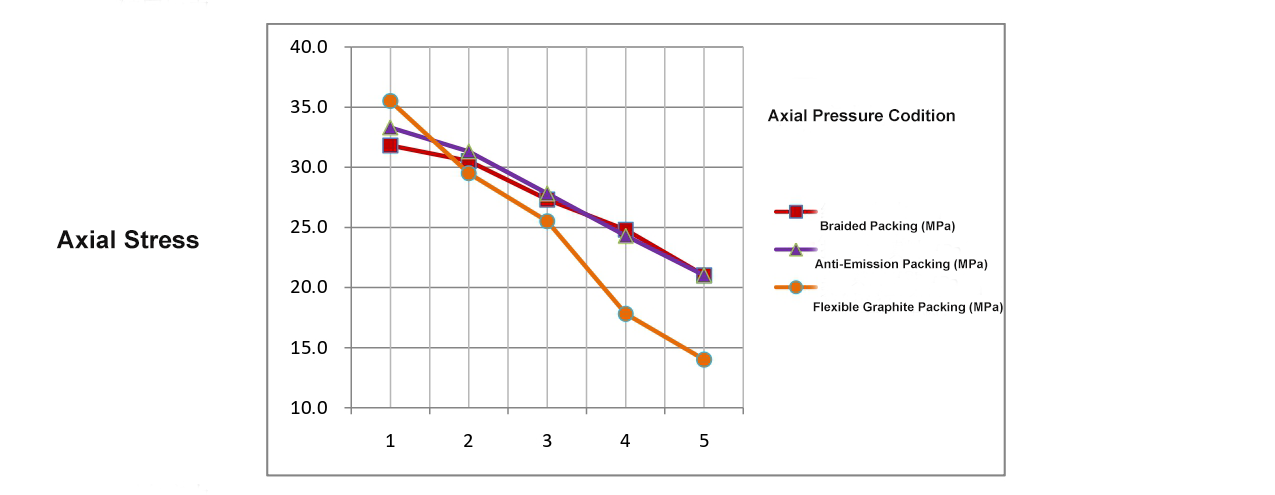
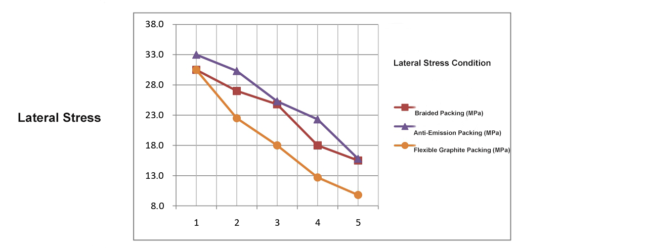
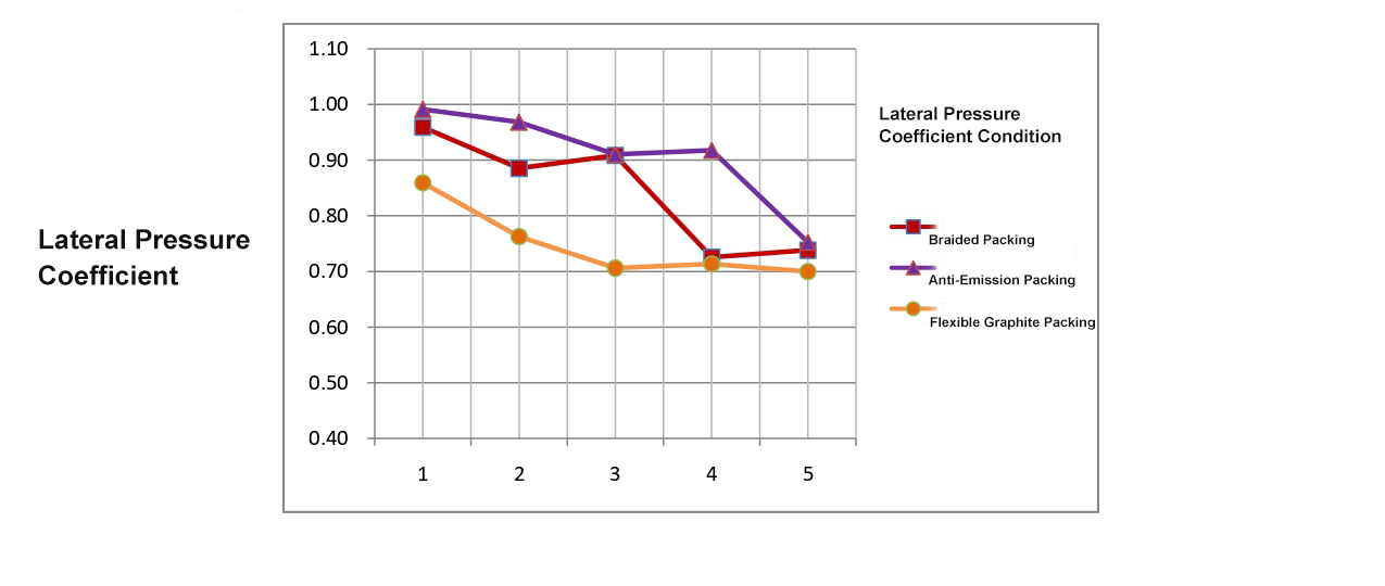
Under the same test ballast load (35MPa), the axial stress and lateral stress of each packing ring were measured using Fuji pressure-sensitive paper from Japan. The lateral pressure coefficient of each packing ring was obtained through calculation. See Figure 1.
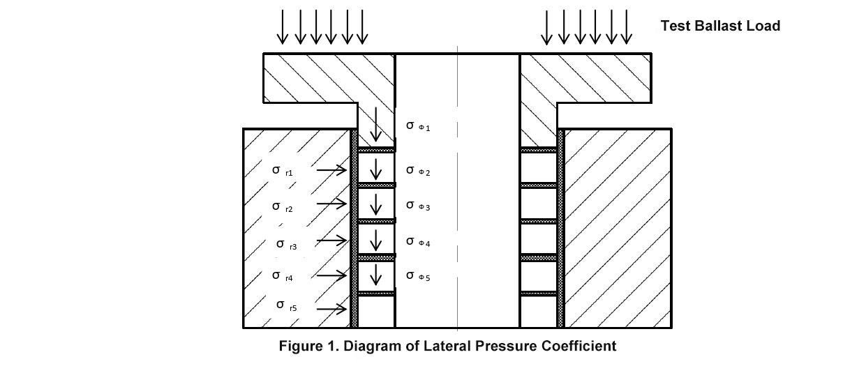
Calculation of lateral pressure coefficient
The lateral pressure coefficient is defined as the ratio of lateral stress to axial stress (n = σr/σφ).
For each packing ring:
1st packing ring lateral pressure coefficient: n1 = σr1/σφ1
2nd packing ring lateral pressure coefficient: n2 = σr2/σφ2
3rd packing ring lateral pressure coefficient: n3 = σr3/σφ3
4th packing ring lateral pressure coefficient: n4 = σr4/σφ4
5th packing ring lateral pressure coefficient: n5 = σr5/σφ5
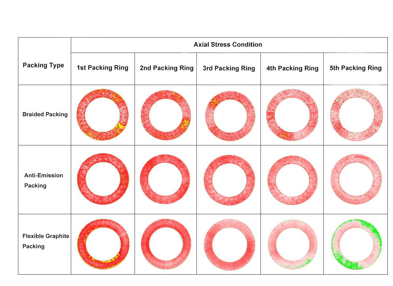
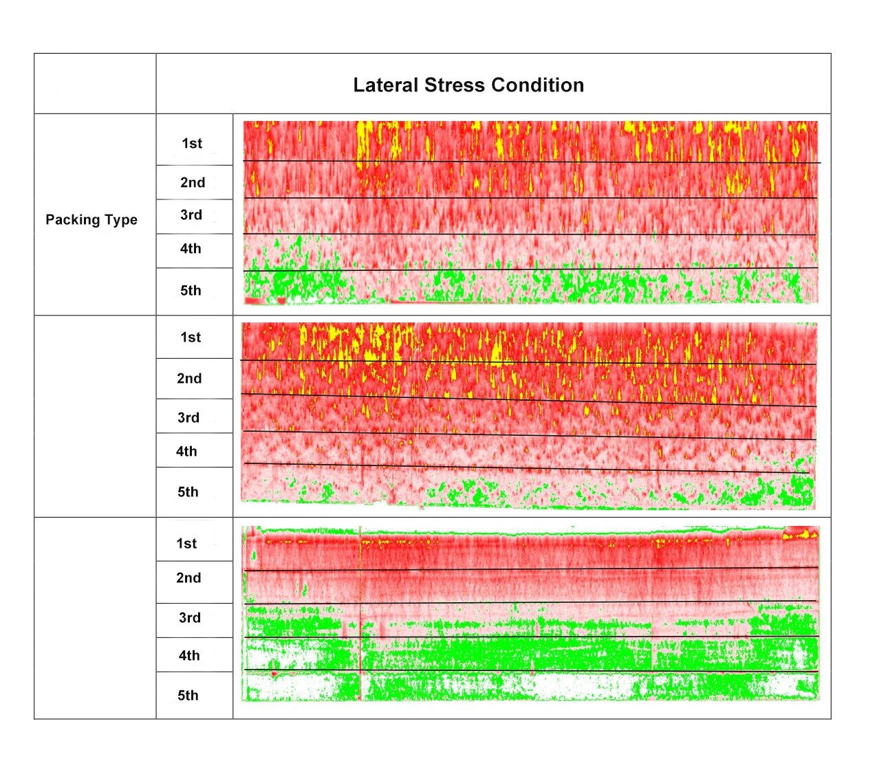
|
Packing Type |
Packing Ring |
Axial Stress (MPa) σφ |
Lateral Stress (MPa) σr |
Lateral Pressure Coefficient |
Avg. Lateral Pressure Coefficient |
|
Braided Packing |
1 |
31.8 |
30.5 |
0.96 |
0.84 |
|
2 |
30.5 |
27.0 |
0.89 |
||
|
3 |
27.3 |
24.8 |
0.91 |
||
|
4 |
24.8 |
18.0 |
0.73 |
||
|
5 |
21.0 |
15.5 |
0.74 |
||
|
Anti-Emission Packing |
1 |
33.3 |
33.0 |
0.99 |
0.91 |
|
2 |
31.3 |
30.3 |
0.97 |
||
|
3 |
27.8 |
25.3 |
0.91 |
||
|
4 |
24.3 |
22.3 |
0.92 |
||
|
5 |
21.0 |
15.8 |
0.75 |
||
|
Flexible Graphite Packing |
1 |
35.5 |
30.5 |
0.86 |
0.75 |
|
2 |
29.5 |
22.5 |
0.76 |
||
|
3 |
25.5 |
18.0 |
0.71 |
||
|
4 |
17.8 |
12.7 |
0.71 |
||
|
5 |
14.0 |
9.8 |
0.70 |
|
Packing Type |
Structure Form |
Axial Stress Condition |
Lateral Stress Condition |
Average Stress (Calculation Basis) |
|
Braided Packing |
Braided graphite strands, no special impregnation process, molded formation. |
Gradually decreases from 1st to 5th pass. Over-compression marks (yellow) in all passes – uneven distribution. |
Gradually decreases. Over-compression (yellow) in 1st–2nd passes, under-stress (green) from 4th pass – uneven. |
0.84 (0.89–0.96 for passes 1–3, 0.73–0.74 for passes 4–5) |
|
Anti-Emission Packing |
Braided graphite strands with special impregnation process, molded formation. |
Gradually decreases. No over-compression marks – even distribution. |
Gradually decreases. Over-compression (yellow) in 1st–2nd passes, under-stress (green) at 5th pass – uneven. |
0.91 (0.91–0.99 for passes 1–4, 0.75 for pass 5) |
|
Flexible Graphite Packing |
Pure graphite material, molded formation. |
Clearly decreasing trend. Over-compression at 1st pass, under-stress (green) from 4th pass – uneven. |
Clearly decreasing trend. Even stress in 1st–2nd passes, under-stress (green) from 3rd pass – uneven. |
0.75 (0.86 for pass 1, 0.70–0.76 for passes 2–5) |
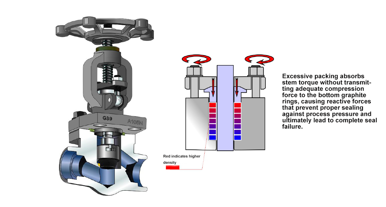
Based on the stress data above, excessively deep packing does not improve sealing performance. On the contrary, over time and with the thermal cycling caused by startup/shutdown operations in the pipeline, it accelerates stress failure. The most direct evidence is the loosening of jack bolt torque.
Therefore, to achieve mass production of small-bore forged steel valves while ensuring 100% low leakage in random installations and full compliance with ISO 15848-1 test performance (400°C, 3 thermal cycles, 310 switching operations), it is necessary to reduce the depth of the stuffing box. This allows the graphite packing to function optimally in terms of mechanical conduction and stress distribution.
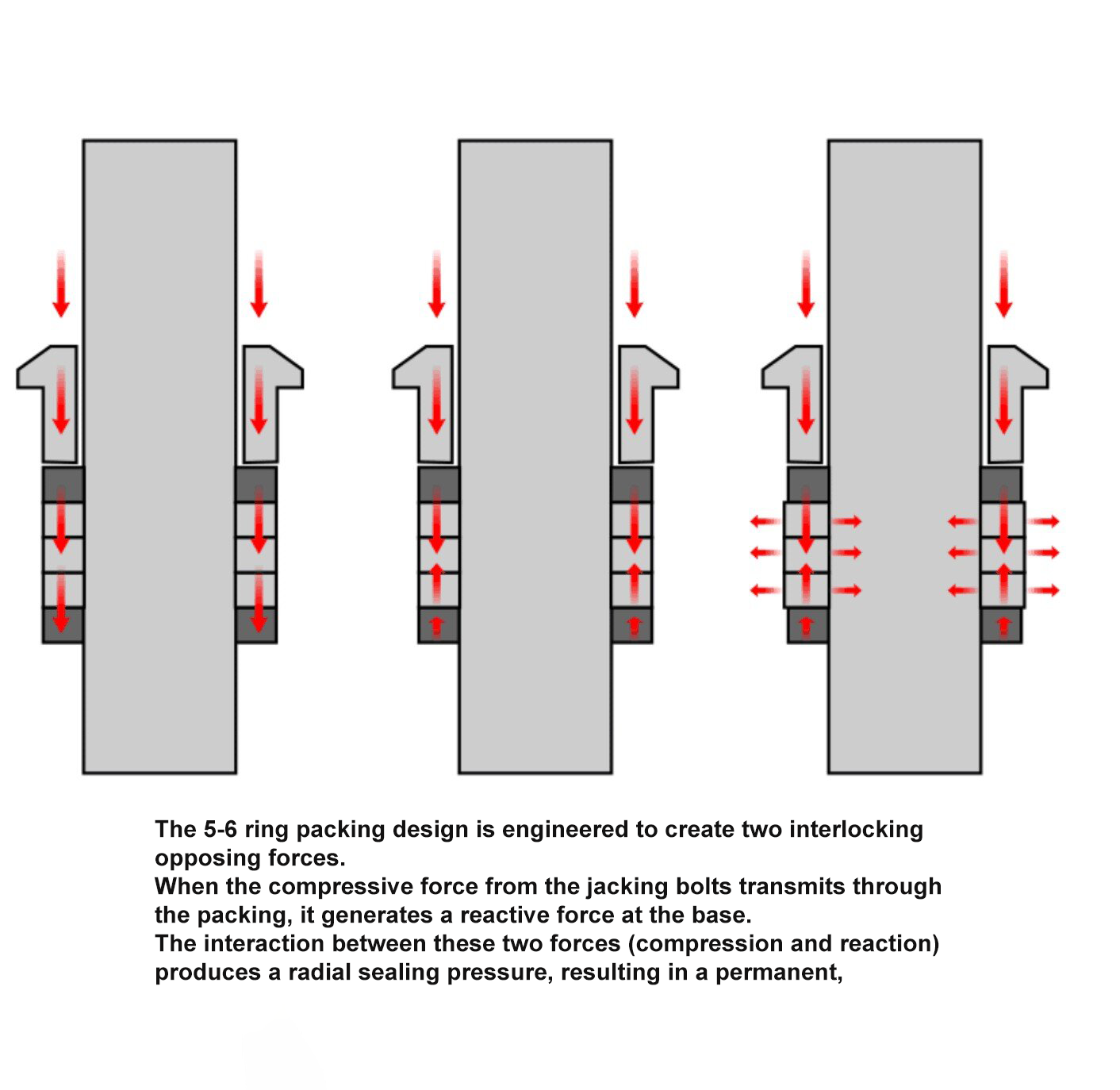
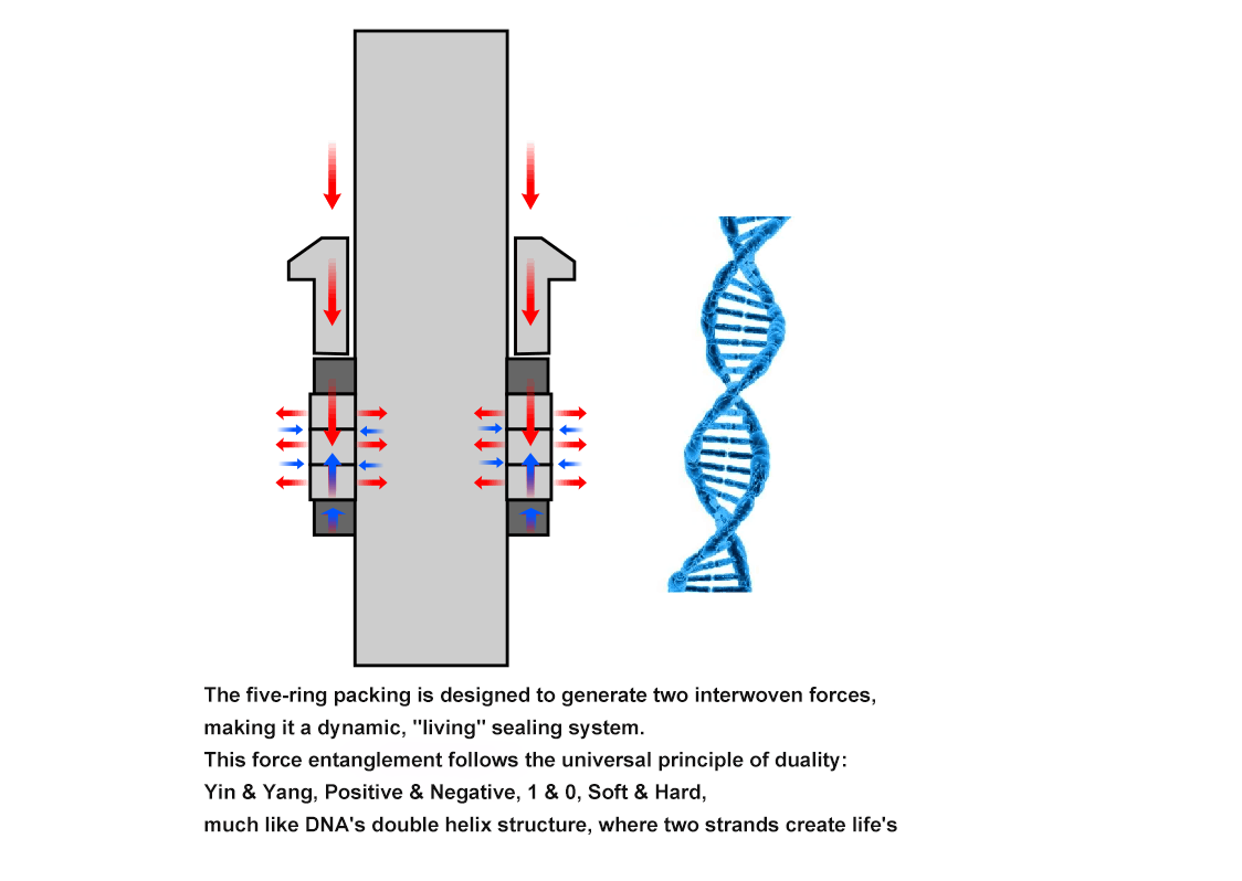
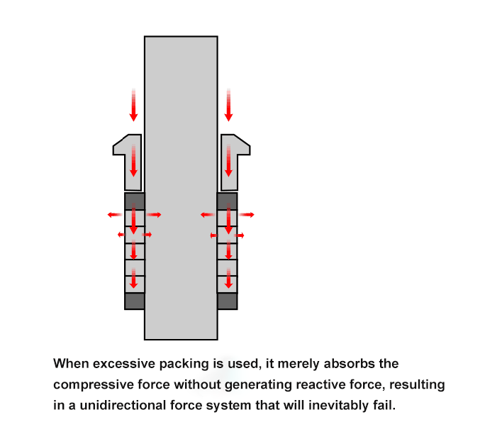
With proper mechanical force guidance, low-leakage packing can indeed achieve bulk randomization, significantly reducing procurement costs while enhancing product performance.