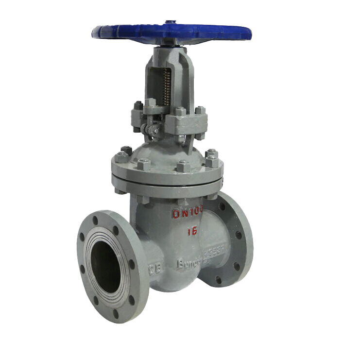
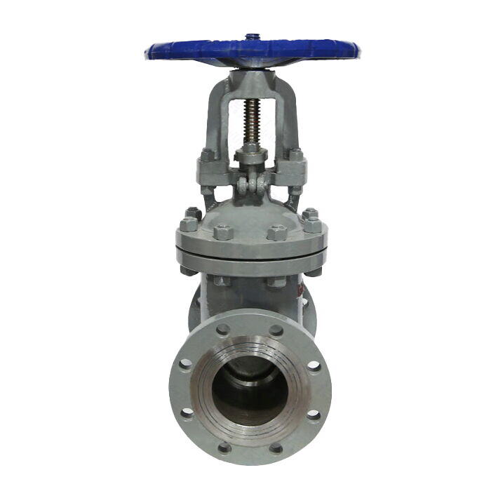
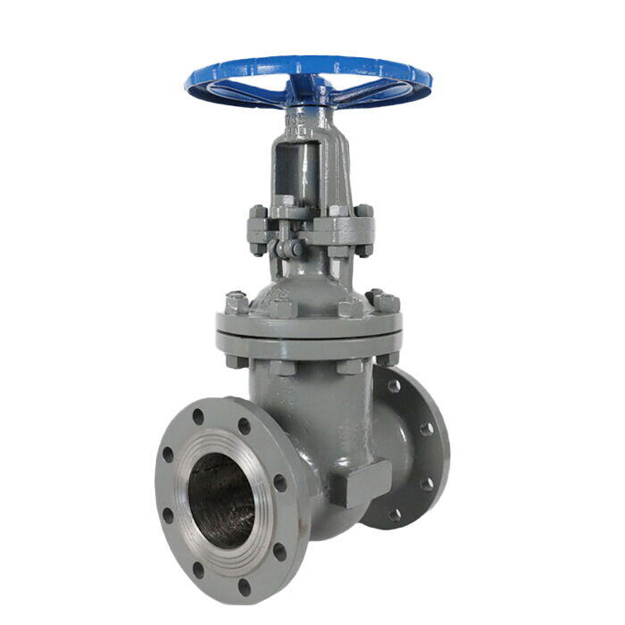
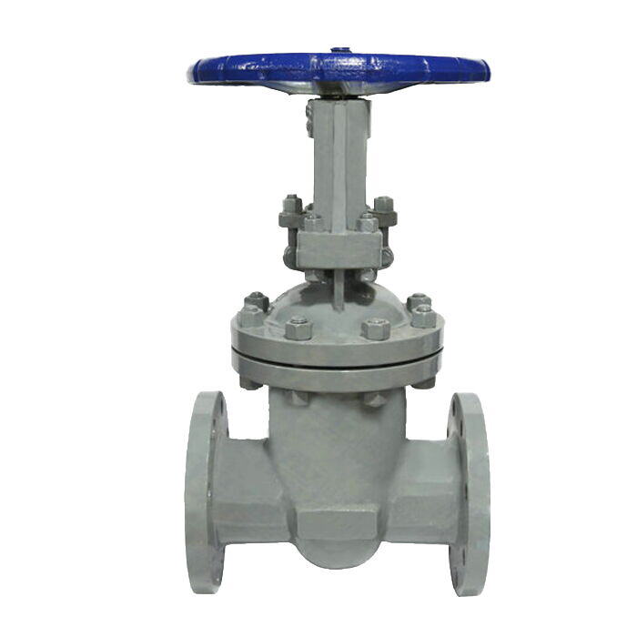
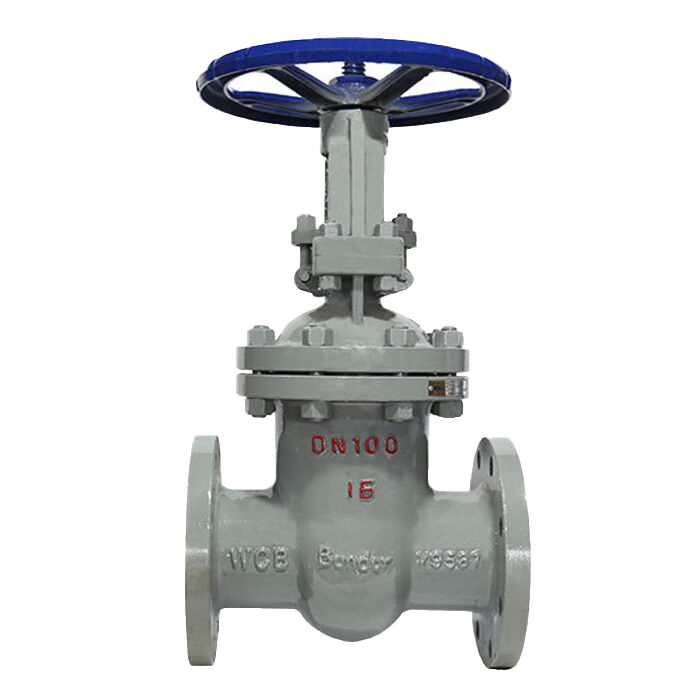
Carbon Steel Wedge Gate Valve, API 600, 1/2-24 Inch, Flanged
(API 624 Additional High Temperature Version)
Key Specifications / Features
The Carbon Steel Wedge Gate Valve Supplier offers a comprehensive range of high-quality wedge gate valves designed in accordance with API 600 and manufactured using ASTM A216 WCB carbon steel. These valves are available in sizes ranging from 1/2 inch to 24 inches (DN15 to DN600) and are rated for pressure classes from 150 LB to 400 LB (PN16 to PN64). They feature flanged ends with options for raised face (RF), ring-type joint (RTJ), and flat face (FF) configurations.
- Model No.: MV-20250626-CSGTV-01
- Hits: 55
- Categories: Cast Steel Gate Valve
- Tags: ASTM A216 WCB Gate Valve, Wedge Gate Valve, Carbon Steel Gate Valve
Detail Information
Product Name: Carbon Steel Wedge Gate Valve
Body Material: ASTM A216 WCB, ZG1Cr18Ni9Ti, ZG0Cr18Ni10Ti, ZG1Cr18Ni12Mo2Ti, ZG0Cr17Ni14Mo2Ti
Size Range: DN15-DN600, 1/2-24 Inch
Nominal Pressure: PN16-PN64, Class 150-400 LB
End Connetion: Flanged (RF, RTJ, FF)
Standards
Design Standard: API 600, GB/T 12234
Structural Length: ISO 10434, GB/T 12221
Flange Connection: EN 1092-1, JB/T 79
Test and Inspection: API 598, API 600, JB/T 9092
Pressure-Temperature Rating: ASME B16.34, GB/T 9131
Product Identification: GB/T 12220
Main Features
The structure is compact, with reasonable design, good valve rigidity, and small flow resistance.
The sealing surface is made of stainless steel and hard alloy, with a long service life.
The packing is flexible, with reliable sealing and easy operation.
The actuation methods include manual, gear, electric, and pneumatic.
The structure is of the flexible wedge Single Disc, Rigid Wedge Single Disc, Double Disc.
Carbon Steel Flanged Gate Valve is suitable for oil refining, chemical industry, petroleum, water supply pipelines, and other working environments that transport steam, oil, and other media.
Main Performance Specifications
Nominal Pressure (MPa) | Test Pressure (MPa) | Shell (Water, Air) (MPa) | Low Pressure Air (MPa) | Working Temperature (°C) | Applicable Medium |
1.6 | 2.4 | 1.8 | 0.6 | ≤425 | Nitric Acid |
2.5 | 3.8 | 2.8 | 0.6 | ≤200 | Nitric Acid |
4.0 | 6.0 | 4.4 | 0.6 | ≤200 | Nitric Acid |
6.4 | 9.6 | 7.0 | 0.6 | ≤200 | Nitric Acid |
Main Materials
Part | ZGICr18Ni9Ti | ZG0Cr18Ni10 | ZG1Cr18Ni12Mo2Ti | ZG0Cr17Ni14Mo2 | WCB |
Body/Cover | ZG1Cr18Ni9Ti | ZG0Cr18Ni10Ti | ZG1Cr18Ni12Mo2Ti | ZG0Cr17Ni14Mo2Ti | WCB |
Trim | ZG1Cr18Ni9Ti | ZG0Cr18Ni10Ti | ZG1Cr18Ni12Mo2Ti | ZG0Cr17Ni14Mo2Ti | 1Cr13 |
Stem | SS 304+PTFE | SS 304L+PTFE | SS 316+PTFE | SS 316L+PTFE | 1Cr13 |
Sealing | ZG1Cr18Ni9Ti | ZG0Cr18Ni10 | ZG1Cr18Ni12Mo2Ti | ZG0Cr17Ni14Mo2Ti | 1Cr13 |
Gasket | 1Cr17Ni2 | 1Cr17Ni2 | 1Cr18Ni9Ti | 1Cr18Ni9Ti | SS 304 |
Nut | 1Cr17Ni2 | 1Cr17Ni2 | 1Cr18Ni9Ti | 1Cr18Ni9Ti | SS 304 |
1.6 MPa Main Dimensions
Size | DN | 15 | 20 | 25 | 32 | 40 | 50 | 65 | 80 | 100 | 125 | 150 | 200 | 250 | 300 | 350 | 400 | 450 | 500 | 600 |
L | mm | 130 | 150 | 180 | 210 | 240 | 270 | 300 | 350 | 400 | 450 | 500 | 600 | 650 | 700 | 800 | 900 | 1000 | 1100 | 1200 |
H | mm | 175 | 180 | 210 | 250 | 285 | 320 | 350 | 400 | 450 | 500 | 550 | 650 | 850 | 900 | 1050 | 1150 | 1250 | 1450 | 1600 |
W | mm | 100 | 120 | 140 | 160 | 180 | 200 | 220 | 240 | 280 | 300 | 350 | 400 | 500 | 550 | 650 | 750 | 800 | 900 | 1000 |
2.5 MPa Main Dimensions
Size | DN | 15 | 20 | 25 | 32 | 40 | 50 | 65 | 80 | 100 | 125 | 150 | 200 | 250 | 300 | 350 | 400 | 450 | 500 | 600 |
L | mm | 130 | 150 | 180 | 210 | 240 | 270 | 300 | 350 | 400 | 450 | 500 | 600 | 650 | 800 | 900 | 1000 | 1100 | 1200 | 1400 |
H | mm | 180 | 180 | 210 | 250 | 280 | 310 | 350 | 400 | 450 | 500 | 550 | 700 | 850 | 950 | 1100 | 1200 | 1350 | 1550 | 1700 |
W | mm | 100 | 120 | 140 | 160 | 180 | 200 | 220 | 240 | 280 | 300 | 350 | 450 | 500 | 600 | 700 | 800 | 900 | 1000 | 1200 |
4.0 MPa Dimensions
Size | DN | 15 | 20 | 25 | 32 | 40 | 50 | 65 | 80 | 100 | 125 | 150 | 200 | 250 | 300 | 350 | 400 |
L | mm | 130 | 150 | 180 | 210 | 240 | 270 | 300 | 350 | 400 | 450 | 500 | 650 | 800 | 950 | 1100 | 1300 |
H | mm | 180 | 180 | 210 | 250 | 280 | 310 | 350 | 400 | 450 | 500 | 600 | 800 | 950 | 1100 | 1300 | 1600 |
W | mm | 100 | 120 | 140 | 160 | 180 | 200 | 220 | 240 | 280 | 300 | 350 | 450 | 500 | 600 | 700 | 800 |
6.4 MPa Main Dimensions
Size | DN | 15 | 20 | 25 | 32 | 40 | 50 | 65 | 80 | 100 | 125 | 150 | 200 | 250 | 300 | 350 | 400 |
L | mm | 170 | 210 | 230 | 240 | 280 | 280 | 320 | 350 | 400 | 450 | 500 | 650 | 800 | 950 | 1100 | 1300 |
H | mm | 180 | 210 | 230 | 240 | 280 | 280 | 320 | 350 | 400 | 450 | 500 | 650 | 800 | 950 | 1100 | 1300 |
W | mm | 120 | 140 | 160 | 180 | 200 | 220 | 240 | 280 | 320 | 350 | 400 | 500 | 600 | 700 | 800 | 900 |
10.0 MPa Main Dimensions
Size | DN | 15 | 20 | 25 | 32 | 40 | 50 | 65 | 80 | 100 | 125 | 150 | 200 | 250 |
L | mm | 190 | 210 | 230 | 240 | 280 | 280 | 320 | 350 | 400 | 450 | 500 | 650 | 800 |
H | mm | 210 | 230 | 240 | 280 | 320 | 350 | 400 | 450 | 500 | 600 | 700 | 850 | 1000 |
W | mm | 120 | 140 | 160 | 180 | 200 | 220 | 240 | 280 | 320 | 350 | 400 | 500 | 600 |
16.0 MPa Main Dimensions
Size | DN | 15 | 20 | 25 | 32 | 40 | 50 | 65 | 80 | 100 | 125 | 150 | 200 |
L | mm | 190 | 210 | 230 | 240 | 280 | 320 | 340 | 390 | 390 | 450 | 525 | 600 |
H | mm | 230 | 240 | 280 | 320 | 350 | 400 | 450 | 500 | 550 | 600 | 700 | 800 |
W | mm | 120 | 140 | 160 | 200 | 240 | 280 | 320 | 360 | 400 | 450 | 550 | 650 |
Note
1. The handwheel, handle, and other actuation mechanisms should not be used as lifting tools (for details, see the product manual).
2. The double flange gate valve should be installed vertically (the handwheel should be at the top, and the handwheel should be removed).
3. The gate valve with bypass valve should be opened before opening the main valve (to balance the pressure difference before opening the main valve).
4. When used with a motor actuator, follow the manufacturer's instructions for installation.
5. If the gate valve is not opened and closed frequently, apply lubricant regularly.
Similar Products


