(API 624 Additional High Temperature Version)
Key Specifications / Features
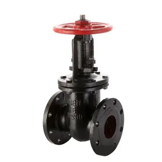
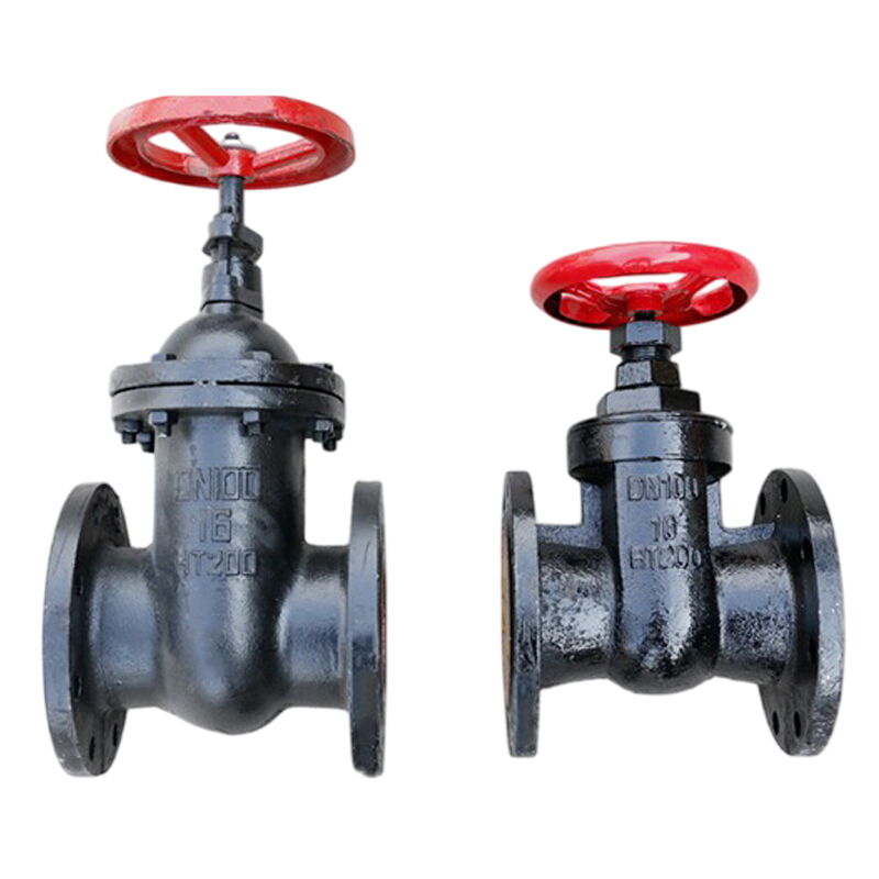
The Gray Cast Iron Gate Valve Factory in China specializes in producing non-rising stem gate valves with HT200 bodies. These valves are designed for DN100 (4 inch) size, with a pressure rating of PN16 and Class 150 LB. They feature RF flanged ends and are handwheel operated, making them suitable for a variety of industrial applications, including water and firefighting systems.
- Model No.: MV-20250701-CSGTV-02
- Hits: 22
- Categories: Cast Steel Gate Valve
- Tags: Gray Cast Iron Gate Valve, HT200 Gate Valve, Non-rising Stem Gate Valve
Detail Information
Product Name: Non-rising Stem Gate Valve
Body Material: HT200, Gray Cast Iron
Size: DN100, 4 Inch
Pressure: PN16, Class 150 LB
End Connection: RF Flanged
Operation: Handwheel
Certificates: TA-Luft, ISO 15848-1, API 622, ect
Product Range
Materials: Gray Cast Iron
Size: DN40-DN600, 1-1/2-24 Inch
Working Pressure: PN10, PN16, Class 150 LB
End Connection: Flanged (RF, RTJ, FF)
Face to Face Standard: ASME B16.10
Testing Standard: API 598
Working Temperature: 0 to 100°C
Medium: Water, Steam
Application: This valve is widely used in power, petroleum, chemical, pharmaceutical, and other industries, suitable for steam, water, oil, and other media in pipeline operations.
Main Component Materials
|
Component Name |
Material |
|
Valve Body, Bonnet, Handwheel |
Cast Iron |
|
Disc |
Cast Iron |
|
Stem |
Carbon Steel |
|
Stem Nut |
Copper |
Main Performance Specifications
|
Model |
Nominal Pressure (MPa) |
Test Pressure |
Applicable Temperature (°C) |
Applicable Medium |
|
|
Strength (Water) MPa |
Seal (Water) MPa |
||||
|
Z41T-10 |
1.0 |
1.5 |
1.1 |
0 to 100°C |
Water, Steam |
|
Z41T-16 |
1.6 |
2.4 |
1.8 |
||
Structure and Working Principle
This valve is connected by flange, in accordance with the GB/T 12232 standard.
The valve consists of a valve body, bonnet, disc, stem, stem nut, and handwheel, etc., and operates by rotating the handwheel to drive the stem nut, which in turn moves the stem up and down, lifting or lowering the disc to achieve the purpose of opening and closing, moving vertically with the flow direction.
Storage, Installation, and Usage Precautions
1. This type of valve should be stored in a dry warehouse and must not be exposed to the open air.
2. For long-term storage, regular maintenance should be performed.
3. This type of valve can be installed on any pipeline, and the handwheel can be positioned arbitrarily.
4. Before installation, the pipeline and valve cavity should be cleaned and pressure tested to meet the requirements. Before testing, the sealing surface should be wiped clean, and all bolts should be checked for tightness. Loose bolts should be tightened evenly, and the packing nut cover should be checked to ensure the packing is tightly pressed and does not hinder the stem from rotating.
5. After installation, the product should not be subjected to excessive external force.
6. The handwheel should be turned clockwise to close and counterclockwise to open.
7. The handwheel should not be used as a lifting device.
8. The working conditions should be consistent with the performance specifications.
9. Regular maintenance should be performed during use.
Dimension Table
|
Model |
DN (mm) |
L |
D |
D₁ |
D₂ |
b-f |
Z-Φd |
H |
D₀ |
|
Z41T-10 |
40 |
165 |
145 |
110 |
85 |
18-3 |
4-Φ18 |
252 |
135 |
|
50 |
178 |
160 |
125 |
100 |
20-3 |
4-Φ18 |
295 |
180 |
|
|
65 |
190 |
180 |
145 |
120 |
20-3 |
4-Φ18 |
330 |
180 |
|
|
80 |
203 |
195 |
160 |
135 |
22-3 |
4-Φ18 |
382 |
200 |
|
|
100 |
229 |
215 |
180 |
155 |
22-3 |
8-Φ18 |
437 |
200 |
|
|
125 |
254 |
245 |
210 |
185 |
24-3 |
8-Φ18 |
508 |
240 |
|
|
150 |
267 |
280 |
240 |
210 |
24-3 |
8-Φ23 |
580 |
240 |
|
|
200 |
330 |
335 |
295 |
265 |
26-3 |
8-Φ23 |
760 |
320 |
|
|
250 |
380 |
390 |
350 |
320 |
28-3 |
12-Φ23 |
875 |
320 |
|
|
300 |
420 |
440 |
400 |
368 |
28-4 |
12-Φ23 |
1040 |
400 |
|
|
350 |
450 |
500 |
460 |
428 |
30-4 |
16-Φ23 |
1195 |
400 |
|
|
400 |
480 |
565 |
515 |
482 |
32-4 |
16-Φ25 |
1367 |
500 |
|
|
450 |
510 |
615 |
565 |
532 |
32-4 |
20-Φ25 |
1498 |
500 |
|
|
500 |
540 |
670 |
620 |
585 |
34-4 |
20-Φ25 |
1710 |
500 |
|
|
600 |
600 |
780 |
725 |
685 |
36-5 |
20-Φ30 |
2129 |
500 |
