Key Specifications / Features
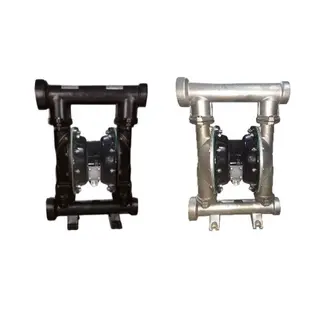
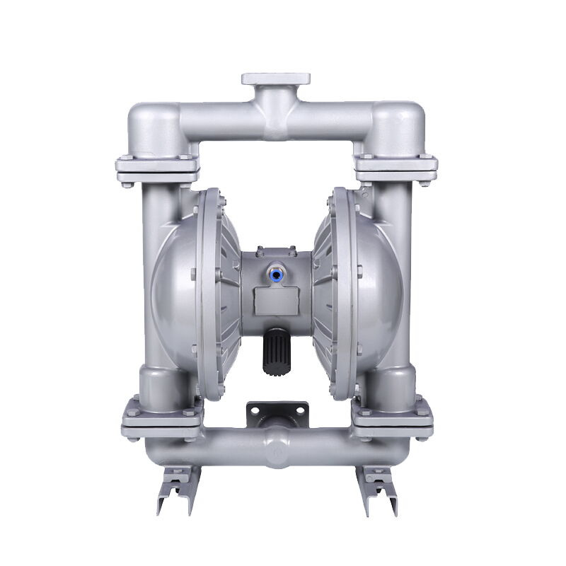
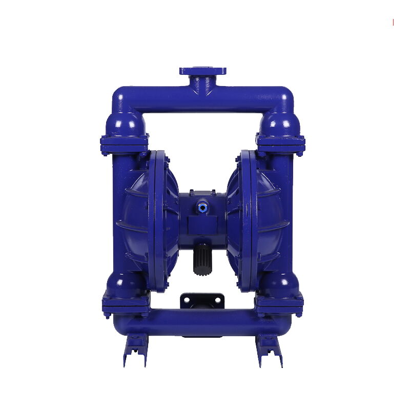
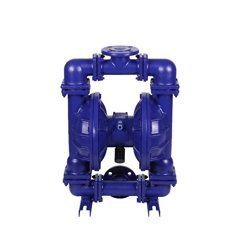
This custom pneumatic diaphragm pump factory offers versatile, high-performance pumps constructed from plastic, aluminum alloy, cast iron, or stainless steel to suit various industrial needs. Available in sizes DN10 to DN100, these pumps deliver a maximum flow rate of 30 m³/h and can handle heads from 0 to 50 meters. Designed for reliable, low-maintenance operation, they are ideal for transferring a wide range of fluids, including corrosive and viscous media, across diverse applications.
- Model No.: MV-20250709-PDP-01
- Hits: 11
- Categories: Pneumatic Diaphragm Pumps
- Tags: Pneumatic Diaphragm Pump, Stainless Steel Diaphragm Pump, Aluminum Alloy Diaphragm Pump
Detail Information
Product Name: Custom Pneumatic Diaphragm Pumps
Material: Engineering Plastic, Aluminum Alloy, Cast Iron, Stainless Steel
Port Sizes: DN10-DN100, 3/8-4 Inch
Maximum Flow Rate: 30 m3/h
Head: 0-50 Meters
Suction Lift: 0-5 Meters
Maximum Air Consumption: 1500 L/min
Maximum Particle Diameter: 10 mm
Recommended Air Compressor Power: Max 11 KW
Product Features
1. Self-Protection Function – Safe and Reliable
Start-up and shutdown are as simple as opening and closing the air valve. Once the pump is overloaded, it will automatically shut down for self-protection. When the load returns to normal, the pump can automatically restart.
2. Self-Priming Start – No Adjustment Needed
No need to fill with priming water. It offers high suction lift and high head. The flow rate can be steplessly adjusted by controlling the opening of the air valve.
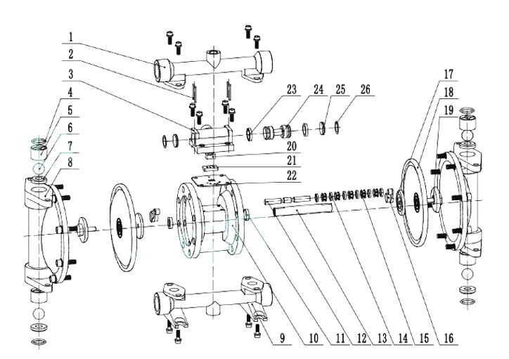
|
No. |
Part Name |
No. |
Part Name |
No. |
Part Name |
No. |
Part Name |
|
1 |
Outlet (Upper Cover) |
2 |
Pin |
3 |
Air Distribution Valve |
4 |
O-ring |
|
5 |
Ball Cover |
6 |
Ball Valve |
7 |
Ball Seat |
8 |
Column |
|
9 |
Inlet (Lower Cover) |
10 |
Intermediate Body |
11 |
Intermediate Shaft Seal |
12 |
Reversing Shaft |
|
13 |
Intermediate Shaft |
14 |
Reversing Shaft Seal |
15 |
Seal Ring Support |
16 |
Support Bracket |
|
17 |
Inner Pressure Plate |
18 |
Rubber Diaphragm |
19 |
Outer Pressure Plate |
20 |
Slider |
|
21 |
Slider Seat |
22 |
Gasket |
23 |
Seal Ring |
24 |
Valve Core |
|
25 |
Air Distribution Valve Gate |
26 |
Gate Seal Ring |
27 |
— |
28 |
— |
QBK Series Diaphragm Pump Parameters
|
Model |
Port Size (DN/NPS) |
Air Inlet |
Flow Rate (m³/h) |
Max Head (m) |
Max Suction Lift (m) |
Outlet Pressure (kgf/cm²) |
Max Particle Diameter (mm) |
Max Air Supply Pressure (bar) |
Max Air Consumption (L/min) |
|
|
QBK-10 |
DN10 |
3/8 Inch |
8 |
0–0.8 |
0–50 |
0–2 |
5 |
1 |
7 |
300 |
|
QBK-15 |
DN15 |
1/2 Inch |
8 |
0–1 |
0–50 |
0–2 |
5 |
1 |
7 |
300 |
|
QBK-25 |
DN25 |
1 Inch |
10 |
0–6 |
0–50 |
0–5 |
5 |
2.5 |
7 |
600 |
|
QBK-40 |
DN40 |
1.5 Inch |
10 |
0–8 |
0–50 |
0–5 |
5 |
4.5 |
7 |
600 |
|
QBK-50 |
DN50 |
2 Inch |
12 |
0–12 |
0–50 |
0–5 |
5 |
8 |
7 |
900 |
|
QBK-65 |
DN65 |
2.5 Inch |
12 |
0–16 |
0–50 |
0–5 |
5 |
8 |
7 |
900 |
|
QBK-80 |
DN80 |
3 Inch |
16 |
0–24 |
0–50 |
0–5 |
5 |
10 |
7 |
1500 |
|
QBK-100 |
DN100 |
4 Inch |
16 |
0–30 |
0–50 |
0–5 |
5 |
10 |
7 |
1500 |
Recommended Matching Reference Table
|
Diaphragm Pump Model |
Recommended Air Compressor Power |
Recommended Filter Press Size |
|
QBK-10 / QBK-15 |
2.2 kW – 3 kW |
Below 10 m2 |
|
QBK-25 / QBK-40 |
4 kW – 5.5 kW |
10–40 m2 |
|
QBK-50 / QBK-65 |
7.5 kW |
40–50 m2 |
|
QBK-80 / QBK-100 |
11 kW |
60–120 m2 |
Troubleshooting for Pneumatic Diaphragm Pumps
|
Malfunction Form |
Cause |
Troubleshooting |
|
No water output or insufficient flow |
1. Insufficient air pressure 3. Valve not opened |
1. Increase air pressure 3. Open the valve |
|
Continuous air exhaust from muffler, pump stops |
1. Damaged air valve seal 3. Silencer blocked 4. Air leakage from connecting rod seal 5. White PTFE sealing wheel in cylinder not tight 6. V-shaped sealing ring worn |
1. Repair or replace air valve seal 3. Clean the silencer 4. Replace connecting rod seal 5. Replace the white PTFE sealing wheel 6. Replace V-shaped sealing ring |
|
Low head |
1. Suction lift too high or too many bends 2. Excessive flow 3. Air pressure too low |
1. Shorten pipeline, reduce bends 3. Adjust air pressure to required head |
|
Excessive noise |
1. Muffler cracked |
1. Replace muffler |
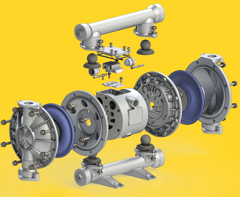
Installation and Maintenance Notes
1. Before installation, ensure all internal components are clean and lubricated. The pump cover and inlet/outlet pipe flanges must be level, with flatness and perpendicularity within 0.1 mm.
Method: Install the pump cover first, but do not overtighten the screws. Then install the inlet/outlet pipes and adjust to ensure balance. Finally, tighten the pump cover screws diagonally.
2. Install an air-water separator or regularly inject oil mist into the cylinder via the air inlet. Use no more than one drop per minute of No. 35 mechanical oil.
3. During disassembly and reassembly, keep all moving parts clean to prevent dust or foreign objects from damaging components.
4. Before disassembling the pump, drain the liquid from the pipeline. Turn the pump upside down to empty internal liquid.
5. If fluid is discharged from the exhaust muffler, check whether the diaphragm is damaged or if the diaphragm fastening screws are loose.
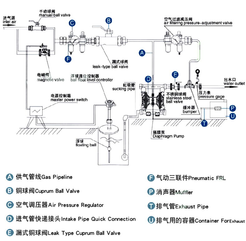
Advantages of Pneumatic Diaphragm Pumps
1. No need to prime the pump; suction lift up to 5 m, head up to 70 m, outlet pressure up to 7 bar.
2. Wide flow range, excellent passability; 125 mm model allows particles up to 10 mm in diameter.
3. Flow and head can be steplessly adjusted via air valve opening (air pressure range: 1–7 bar).
4. Operating environment: 5–65°C; medium temperature range: 0–100°C.
5. No rotating parts or shaft seals; the medium is completely isolated from moving parts. No leakage, suitable for toxic, volatile, or corrosive fluids.
6. No electricity required; safe for use in flammable or explosive environments.
7. Easy to use and reliable; simply open or close the air valve to start or stop. If overloaded, the pump automatically shuts down and restarts when load returns to normal.
8. Simple structure with few wear parts; easy to install and maintain. The medium does not contact the air valve or connecting rods, avoiding performance degradation due to wear.
9. Can handle viscous liquids (viscosity up to 8,000 cP).
Similar Products
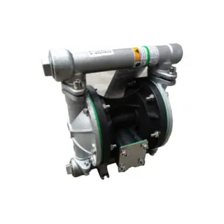
Stainless Steel Diaphragm Pump, 1/2-1 IN, 0-35 LPM, Pneumatic
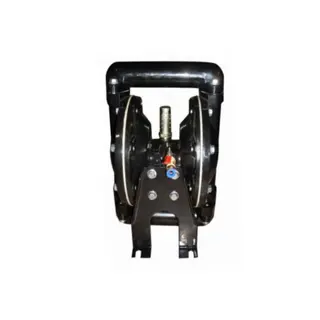
Aluminum Alloy Diaphragm Pump, 1 IN, 0-110 L/min, Pneumatic
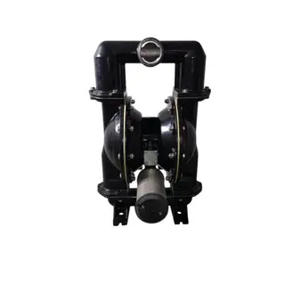
DN80 Pneumatic Diaphragm Pump, 0-890 L/min, 0-70 Meters Lift
