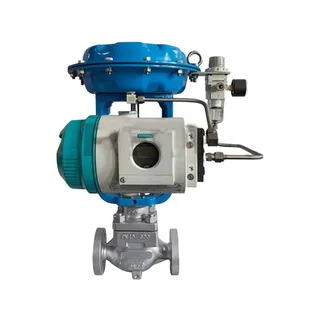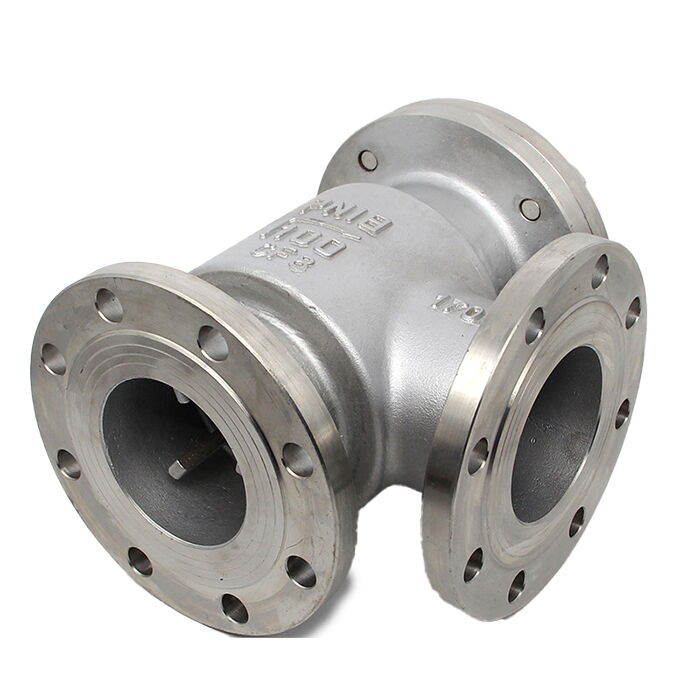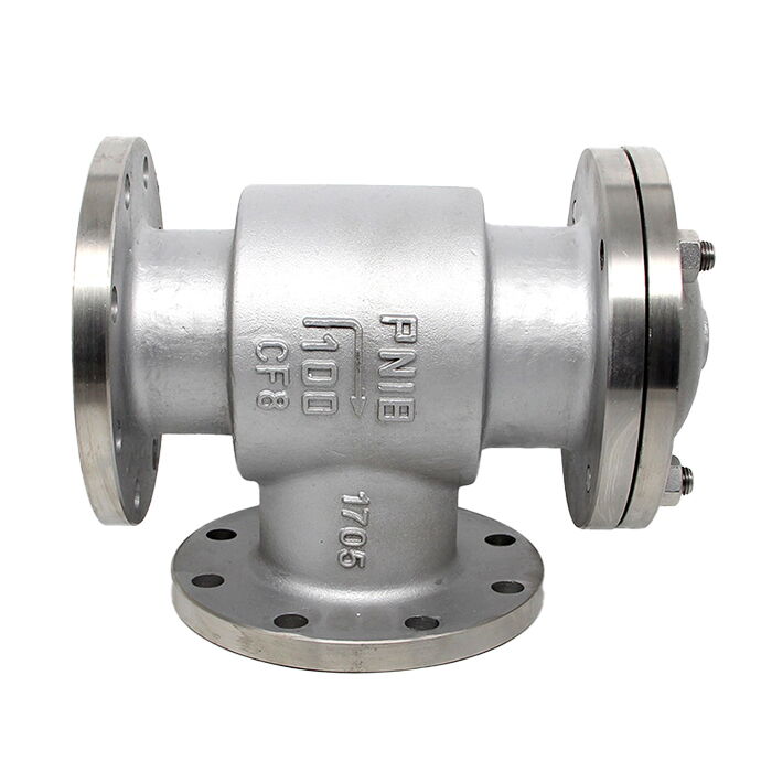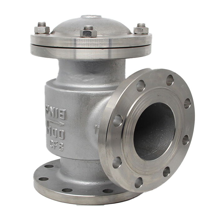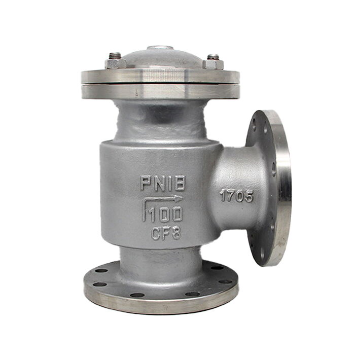
(API 624 Additional High Temperature Version)
Key Specifications / Features
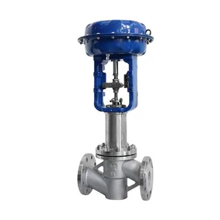
The Hydraulic Water Level Control Valve features an Angle Type Body made from ASTM A351 CF8 Cast Stainless Steel, ensuring durability and corrosion resistance. With a DN100 (4 Inch) size and a pressure rating of PN18 (Class 150 LB), this valve is designed for high-performance applications. It comes with flanged ends for easy installation and secure connections, making it ideal for precise water level control in various industrial settings.
- Model No.: MV-20250704-LECV-01
- Hits: 21
- Categories: Low Emission Control Valves
- Tags: ASTM A351 CF8 Control Valve, Hydraulic Control Valve, Water Level Control Valve
Detail Information
Product Name: Hydraulic Water Level Control Valve
Body Type: Angle Type
Body Material: ASTM A351 CF8
Size: DN100, 4 Inch
Pressure: PN18, Class 150 LB
End Connection: Flanged
Product Range
Size Range: DN80-DN400, 3-12 Inch
Pressure Range: 1-2.5 Mpa, PN10-PN25
Body Material: Carbon Steel, Stainless Steel, Ductile Iron
Sealing Material: NBR, Neoprene
End Connection: Flanged
Main construction: Main Valve, Pilot Valve, Floating Ball Valve
Introduction to Hydraulic Water Level Control Valve
The water level control valve is suitable for automatic water supply systems in various water tanks (pools) in industrial and mining enterprises, civil buildings, and can also be used as a control valve for boiler feedwater systems.
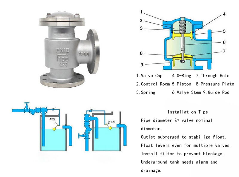
Working Principle of Hydraulic Water Level Control Valve
When the water level in the water tank or pool drops, the float valve opens to discharge water. The water pressure inside the pipe lifts the valve plug, sealing the valve, and the valve opens to supply water. When the water level rises to the control level, the float valve closes, the water pressure decreases, the valve plug seals the valve, and the valve stops supplying water.
Technical Parameters of Hydraulic Water Level Control Valve
Applicable Medium: Clean water
Operating Pressure:
H142X-4T-A, H142X-4-A: 0.05-0.4MPa
H142X-10-A: 0.05-1MPa
Material Temperature: ≤PREFFX = ST160°C
Performance Features of Hydraulic Water Level Control Valve
Uses hydraulic pressure control, with a reasonable structure.
Stable operation. It can withstand the specified operating pressure without water hammer.
Light weight, small size.
Easy to install and maintain.
Installation Methods and Precautions for Hydraulic Water Level Control Valve
The hydraulic water level control valve should be installed vertically on the water pipe, and the control pipe, valve, and float valve should be connected tightly to the valve. The water level control valve and the water pipe should be connected with H142X-4T-A as 0.6MPa standard flange; H142X-10-A as 1MPa standard flange. The water pipe diameter should be greater than or equal to the valve diameter, and the outlet should be lower than the float ball valve. The float ball valve should be installed at a distance of more than one meter from the water pipe, and the water pipe should be higher than the water level by about one meter to prevent water from flowing back. When installing the valve, the float ball valve should be installed at the same level as the water tank. The valve should be installed with a sufficient air gap to prevent water from flowing back. To prevent impurities and sand from entering the valve and causing malfunction, a filter should be installed.
|
Model |
Specification (DN) |
G (in) |
Small (mm) |
A (mm) |
B (mm) |
H (mm) |
n-d (mm) |
Weight (kg) |
|
H142X-4T-A |
80 |
1/2 |
150 |
115 |
120 |
255 |
4-19 |
16 |
|
100 |
1/2 |
170 |
132 |
150 |
294 |
4-19 |
24 |
|
|
150 |
3/4 |
225 |
140 |
200 |
370 |
8-19 |
50 |
|
|
H142X-4-A |
200 |
3/4 |
280 |
190 |
210 |
455 |
8-19 |
82 |
|
250 |
3/4 |
335 |
220 |
240 |
525 |
12-19 |
144 |
|
|
80 |
1/2 |
160 |
145 |
145 |
328 |
8-19 |
20 |
|
|
100 |
1/2 |
180 |
160 |
160 |
357 |
8-19 |
29 |
|
|
150 |
3/4 |
240 |
180 |
200 |
415 |
8-23 |
60 |
|
|
H142X-10-A |
200 |
1 |
295 |
215 |
230 |
482 |
8-23 |
95 |
|
250 |
1 |
350 |
245 |
260 |
555 |
12-23 |
160 |
|
|
300 |
1-1/4 |
400 |
260 |
290 |
620 |
12-23 |
210 |
|
|
350 |
1-1/4 |
460 |
310 |
310 |
715 |
16-23 |
280 |
|
|
400 |
1-1/4 |
515 |
370 |
370 |
845 |
16-28 |
Similar Products
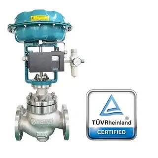
Pneumatic Single Seated Control Valve, A351 CF8, DN80, PN16
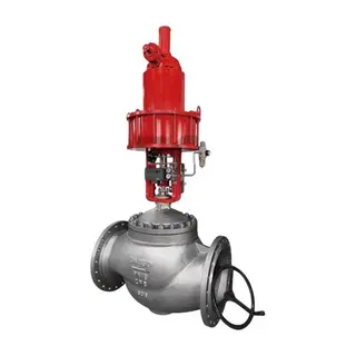
Pneumatic Cut-off Control Valve, ASTM A351 CF8, DN450, PN16
Acid Resistant Control Valve, 1/2-8 Inch, 150 LB, Pneumatic
