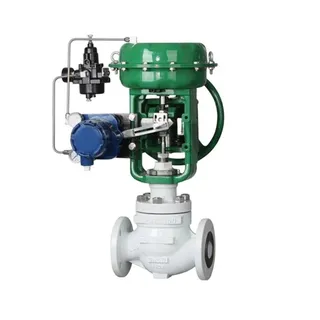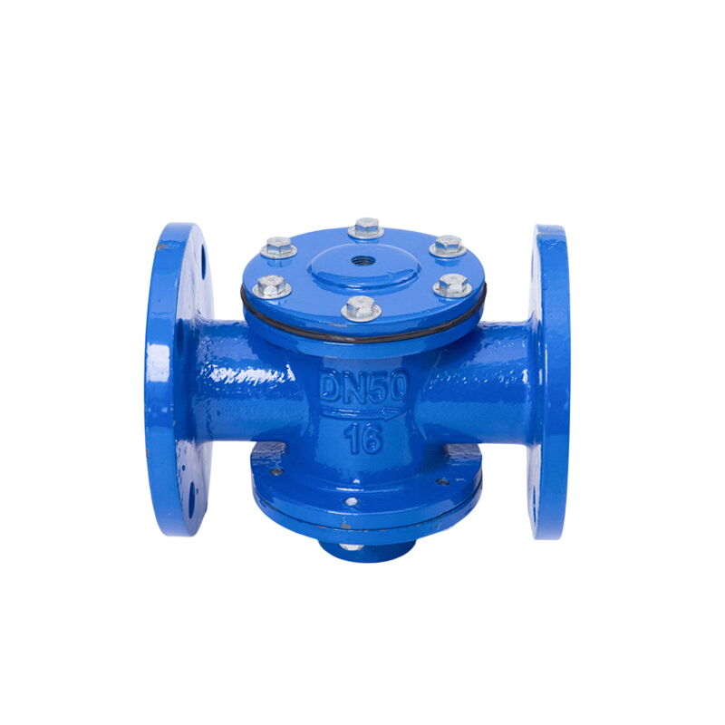
(API 624 Additional High Temperature Version)
Key Specifications / Features
Discover high-quality differential pressure control valves from a top factory. These adjustable valves feature durable ductile iron bodies and components made from carbon or stainless steel, ensuring robust performance and longevity. Available in sizes ranging from DN32 to DN500, they are designed to meet various industrial needs. With pressure ratings of PN10, PN16, and PN25, these valves offer reliable control and are equipped with flanged ends for secure and easy installation.
- Model No.: MV-20250703-LECV-04
- Hits: 7
- Categories: Low Emission Control Valves
- Tags: Differential Pressure Control Valve, Ductile Iron Control Valve, Carbon Steel Control Valve
Detail Information
Product Name: Adjustable Differential Pressure Control Valve
Material: Ductile Iron, Carbon Steel, Stainless Steel
Size: DN32-DN500, 1-1/4 Inch - 20 Inch
Rated Pressure: 1.0, 1.6, 2.5 MPa, PN10, PN16, PN25, Class 150, 300 LB
Applicable temperature: 0°C to 80°C, 80°C to 150°C (custom-made)
Medium: Water
End Connection: Flanged
Control pressure range:
Set pressure difference: 0.03 MPa, accuracy ±10%
Adjustable pressure difference: 0.03 - 0.15 MPa, accuracy ±15%
Adjustable differential pressure control valve is a flow control device used in heating and air conditioning duct systems. It can manually or automatically adjust the opening of the valve according to needs to control the flow and maintain a set differential pressure.
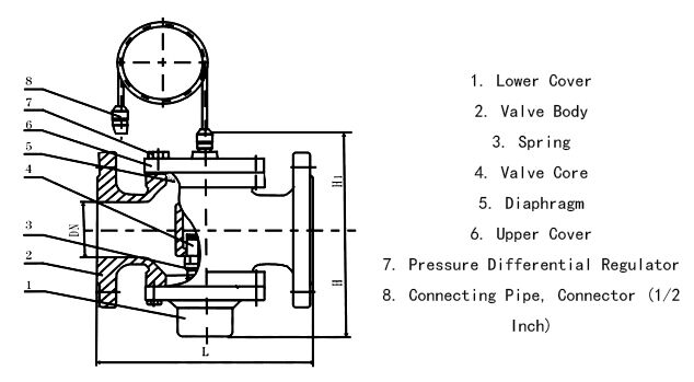
Main Features of Adjustable Differential Pressure Control Valve
Flow Adjustment: The adjustable differential pressure control valve can manually or automatically adjust the valve opening according to requirements to control the flow in the duct system.
Differential Pressure Control: This type of valve can maintain a set differential pressure by adjusting the valve opening, ensuring the pressure within the duct system is within a reasonable range.
Precision: The adjustable differential pressure control valve has a relatively high degree of control precision, capable of meeting the requirements for applications with higher demands for flow and differential pressure control precision.
Multiple Control Methods: The adjustable differential pressure control valve can be adjusted manually via a handwheel, or controlled automatically by an electric actuator or other means to achieve flexible and diverse flow and differential pressure adjustments.
Main Dimensions and Performance Parameters
|
DN (mm) |
Connection Method |
L (mm) |
H |
H1 |
Flow Rate (m³/h) |
Applicable Medium |
Applicable Temperature |
|
32 |
Flange |
200 |
91 |
94 |
1-4 |
Water |
0°C to 80°C |
|
40 |
200 |
147 |
112 |
1.5-6 |
|||
|
50 |
200 |
120 |
112 |
2-8 |
|||
|
65 |
210 |
125 |
120 |
3-12 |
|||
|
80 |
260 |
188 |
133 |
5-20 |
|||
|
100 |
280 |
208 |
160 |
10-30 |
|||
|
125 |
290 |
226 |
175 |
15-45 |
|||
|
150 |
336 |
258 |
195 |
30-80 |
|||
|
200 |
405 |
301 |
230 |
40-180 |
|||
|
250 |
450 |
367 |
265 |
100-300 |
|||
|
300 |
600 |
430 |
300 |
150-500 |
|||
|
350 |
504 |
340 |
200-700 |
||||
|
400 |
396 |
400 |
275-900 |
||||
|
500 |
480 |
490 |
430-1400 |
Note: Flange dimensions according to GB/T 17241.6
Similar Products
Top Guided Control Valve, 1/2-8 Inch, CL150-600, Unbalanced
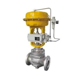
Cage Guided Control Valve, CS, SS, AS, 1.5-24 IN, Single Seat
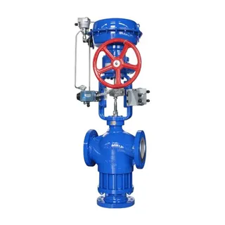
Pneumatic 3-Way Control Valve, Diverting/Converging, 1-20 IN
